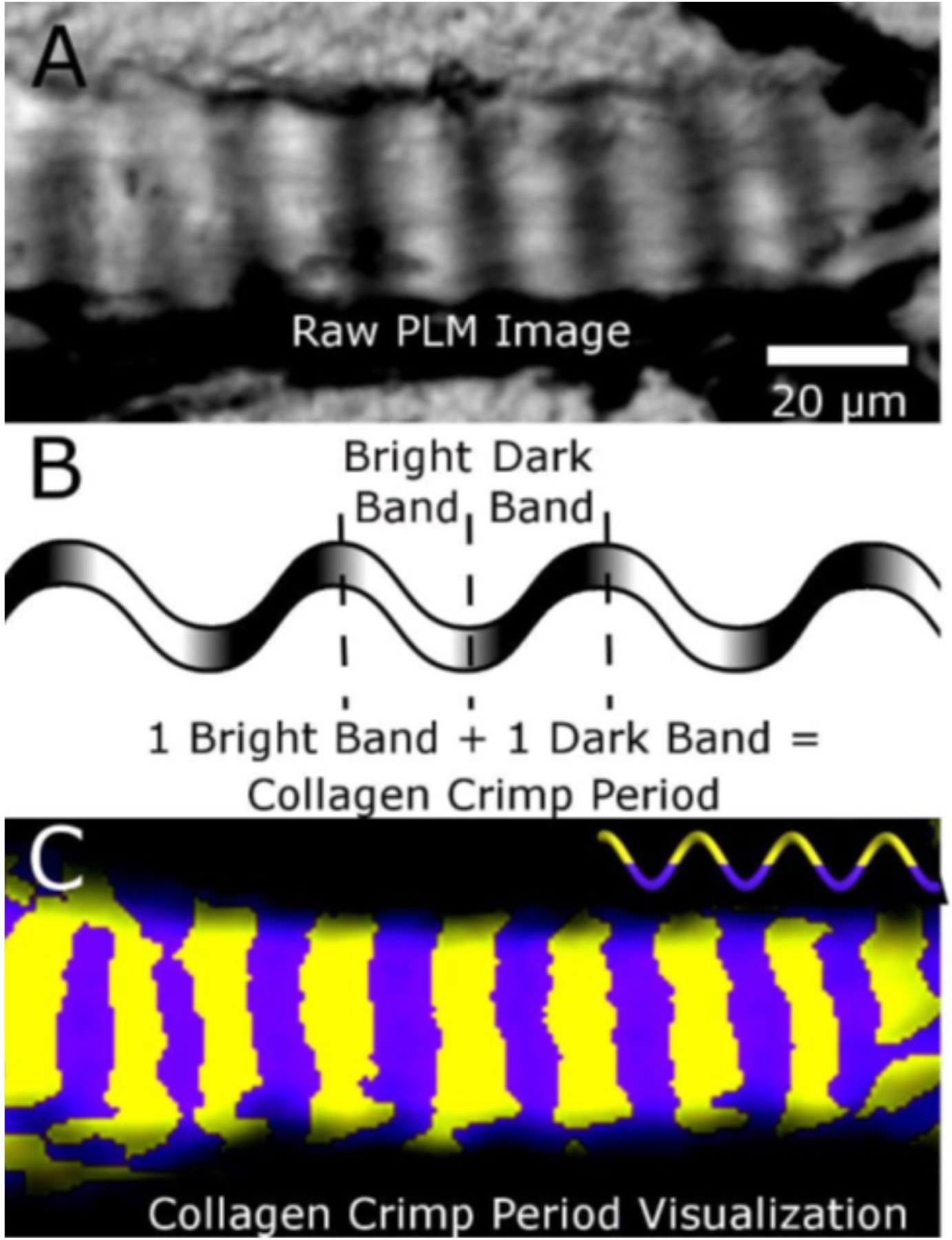
Figure 10:

Collagen crimp period visualised using PLM. A) An LC beam appears banded when imaged with PLM. B) Adding the lengths of one bright band and one dark band makes one collagen crimp period. C) Processing several “raw” PLM images with various filter orientations, it is possible to pseudocolour half periods as alternating yellow and purple bands that help visualize the crimp. Note that the crimp bands are fairly uniform and perpendicular to the longitudinal axis of the LC beam. This crimp pattern helps reduce shearing and torsion within the LC beam when loaded longitudinally. Note that crimp period is only one aspect of fibre crimp. Figure adapted from (Jan et al., 2017a) with permission of the Association for Research in Vision and Ophthalmology.
