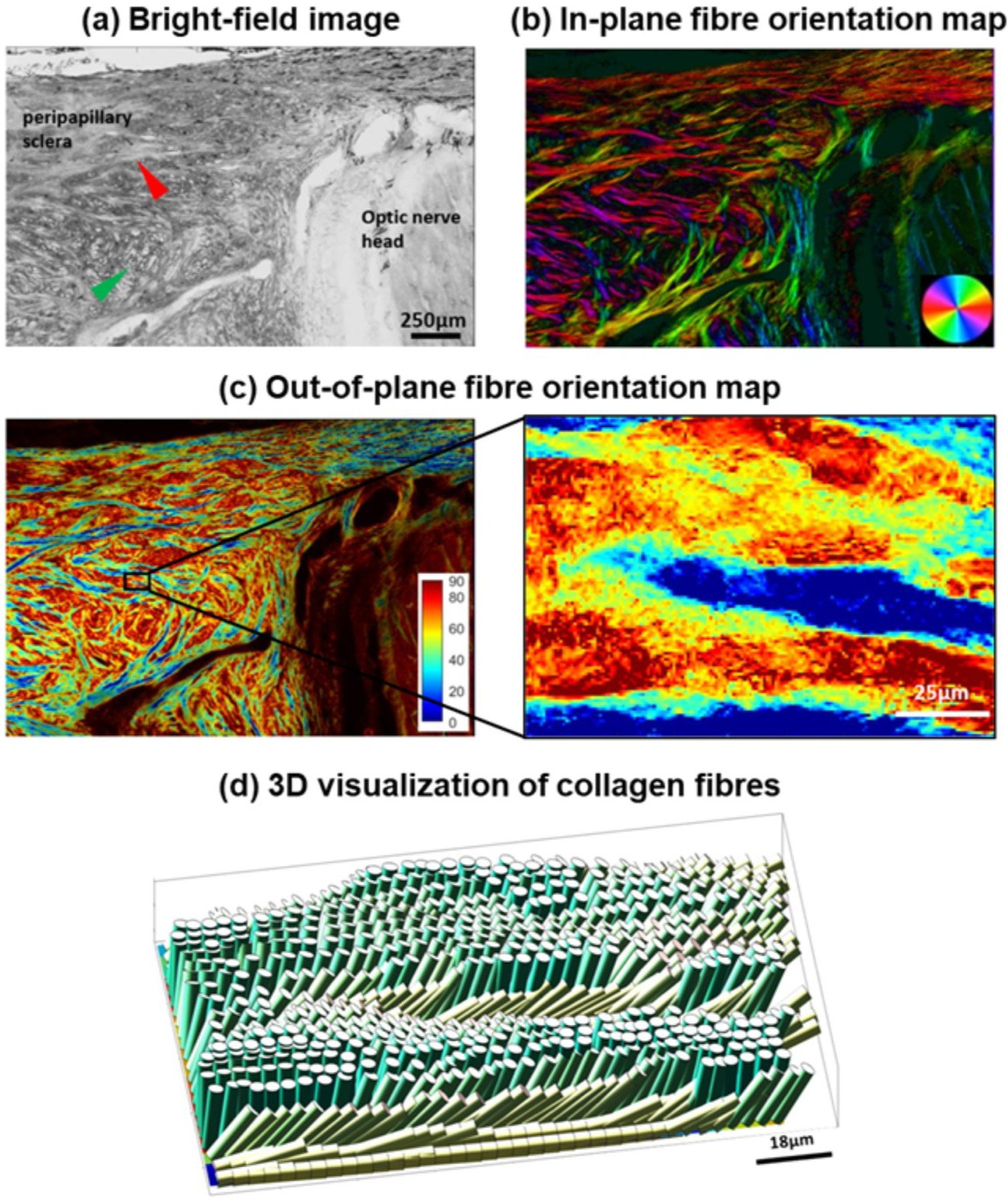
Figure 14:

Application of 3DPLM to the posterior pole of a sheep eye. The 3D orientation of the fibres can be separated into in-plane and out-of-plane orientations, where the plane is that of the section. (a) Bright field image of a cryosection with red and green arrowheads pointing to long in-plane fibre bundles and out-of-plane fibre bundles, respectively; (b) In-plane fibre orientation map showing both in-plane fibre morphology and orientation. Colours indicate the in-plane fibre orientation; (c) Out-of-plane fibre orientation map highlighting fibre bundles. Colours indicate the out-of-plane fibre orientation, from fully in-plane (blue) to perpendicular to the plane (maroon); (d) Out-of-plane fibre orientation of small region of interest shown in (c); (e) 3D visualization of collagen fibres. Figure adapted from (Yang et al., 2018b) with permission of the Journal of Biophotonics.
