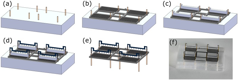
Fig 4. Assembly steps of the quad-thruster device.
(a) Fiber-optic glass poles placed into the holes of the holding jig. (b) Grid is then placed on holding jig through the poles. Note: grid thickness exaggerated for 3D view. (c) Four spacing jigs placed on each single collector grid. (d) Four emitters are slid into the poles on top of spacing jigs. (e) Dimetric view of a quad-thruster after the jigs are removed. (f) Picture of a quad-thruster fully assembled in the external jig-1 that is used for assembly.

