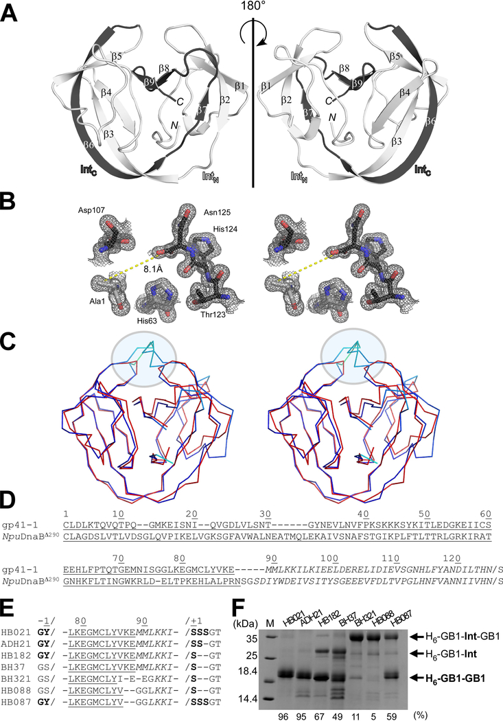
Fig. 2.
Crystal structure of the C1A variant of the engineered cis-splicing gp41–1 intein. (A) Ribbon representations of the gp41–1 intein structure. The region corresponding to the C-terminal split fragment (IntC) is colored in dark grey. N and C indicate N- and C-termini, respectively. (B) Stereoview of the active site residues of the gp41–1 intein structure. The distance between the Cβ atom of Ala1 and the carbonyl carbon of Asn125 is shown. (C) Stereo-view of an overlay of the crystal structures of the gp41–1 intein (red) and the closest related structure, the NpuDnaB mini-intein (blue) (PDB: 4o1r). A circle indicates the C35 and C2-symmetry-related N35 sites where additional residues are inserted in NpuDnaB mini-intein. (A-C) Structures were drawn using PyMOL. (D) Sequence alignment between the cis-splicing gp41–1 intein and NpuDnaB mini-intein (NpuDnaBΔ290). Underlined and italicized letters indicate sequence corresponding to the N- and C-terminal split fragments, respectively. (E) Engineering of the gp41–1 intein in the loop and splicing junction regions and their effects on protein splicing in cis. HB021, ADH21, HB182, BH37, BH321, HB088, and HB087 indicate the short names for different constructs with the sequence variations shown in the sequence alignment. (D-E) Sequence alignments were generated using Clustal Omega. (F) SDS-PAGE analysis of the cis-splicing activity of the engineered gp41–1 intein variants. M stands for molecular weight markers. H6-GB1-Int-GB1 indicates unspliced precursor proteins. H6-GB1-GB1 indicates cis-spliced products with various junction sequences causing minor variations in the migration profile. H6-GB1-Int indicates an off-pathway C-cleavage product. The splicing efficiency in percent quantified from the gel is shown at the bottom. The gel summarizes representative results of one to four individually performed experiments per construct.

