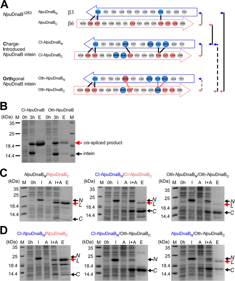
Fig. 5.
Engineering of the cis-splicing NpuDnaB mini-intein toward an orthogonal split intein pair. (A) Schematic comparison between the original and engineered NpuDnaB mini-inteins in the regions corresponding to β3 and β6 in the gp41–1 intein structure. Solid lines indicate possible favored charge interactions. Dotted red lines indicate possible unfavored charge interactions. Pairs of the split inteins tested in panels B and C are indicated by arrows and lines, where broken lines indicate poor or no trans-splicing. (B) Cis-splicing of the charge-introduced CI-NpuDnaB and the designed orthogonal Oth-NpuDnaB mini-inteins by SDS-PAGE analysis. Cis-spliced products and excised inteins are indicated by red and black arrows, respectively. M, 0h, 3h, and E above the lanes indicate molecular markers, before induction, 3 hours after induction, and elution fraction from Ni-NTA columns. The gel of a single experiment is shown. (C) Trans-splicing of split inteins derived from the NpuDnaB intein (left), Charge-Introduced (CI)-NpuDnaB intein (middle), and the designed orthogonal (Oth)-NpuDnaB intein (right) by splitting at the canonical split site. The results of one to three individual experiments for each combination are shown. (D) Test for orthogonality between split inteins derived from the NpuDnaB intein. SDS-PAGE analysis of trans-splicing for the pairs of CI-NpuDnaBN/NpuDnaBC (left), CI-NpuDnaBN/Oth-NpuDnaBC (middle), and NpuDnaBN/Oth-NpuDnaBC (right) indicated by arrows with solid and broken lines in panel A. The results of one or two individual experiments per combination are shown. For panels C and D, N and C with arrows indicate the bands for the N- and C-terminal precursors, respectively. L indicates the ligated product by trans-splicing. M, 0h, I, A, I+A, and E stand for molecular markers, before induction, IPTG induction, arabinose induction, both IPTG and arabinose induction, and elution fraction from Ni-NTA spin columns, respectively.

