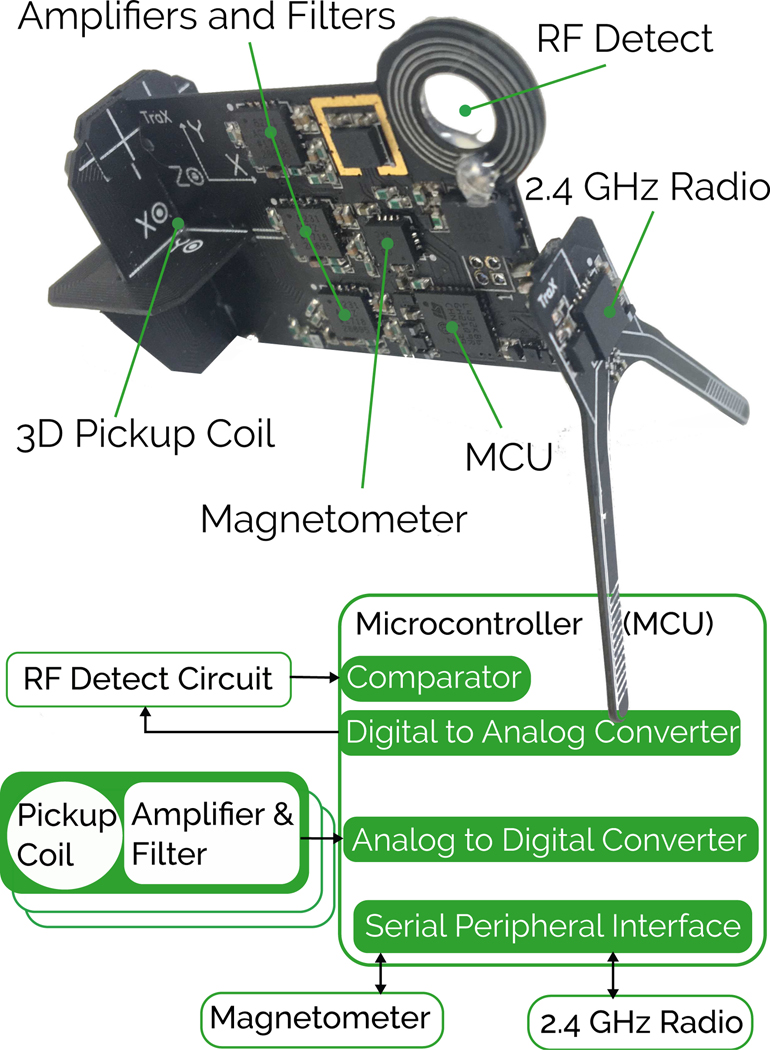
Fig. 2.
The WRAD hardware used to measure the signals presented in this work. The slew vector sensor is constructed from 3 PCB inductors (‘Z’ on the main PCB, ‘X’ and ‘Y’ on separate PCBs) each precisely cut with slots to allow them to be mounted mutually orthogonal to each other, representing the principal axes of the WRAD co-ordinate frame (please note that the silkscreen markings XYZ define the ijk co-ordinate frame of Figure 1).

