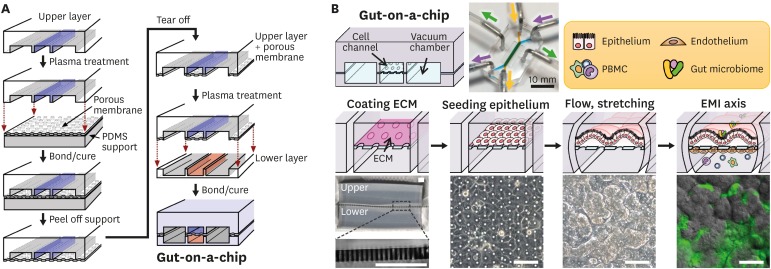
Figure 1. Microfabrication of a human gut-on-a-chip and microfluidic cultures of the EMI axis. (A) The gut-on-a-chip microfluidic device is fabricated using soft lithography method by placing each compartment in a layer-by-layer approach to build the central cell culture chamber with an upper (blue) and a lower (orange) microchannel (1 mm×1 cm×200 μm, width×length×height) and bi-lateral vacuum chambers (grey). (B) A schematic flowchart shows sequential steps to recreate intestinal EMI in a gut-on-a-chip by coating the central cell microchannels using ECM (“coating ECM”), followed by the attachment of epithelium (“seeding epithelium”), application of flow and mechanical stretching motions (“flow, stretching”), and maintenance of the steady-state physiological milieu including gut microbiome and immune cells (“EMI axis”). An inset photograph (top middle) shows a fully equipped gut-on-a-chip device linked to the silicone tubing that supplies culture medium (purple or yellow-green arrow heads) or cyclic vacuum suctions that induce peristalsis-like motions (green arrow heads). Schematics of the representative experimental steps (middle row) and corresponding micrographs of either the device or the cell morphology (bottom row). A zoomed-in snapshot in the left bottom shows the part (a light grey dashed box) of a PDMS porous membrane (25 µm in thickness). A phase contrast image in “seeding epithelium” shows the formation of an intestinal epithelial monolayer in the upper microchannel. An image in “flow, stretching” displays the villous growth under mechanically dynamic physiological conditions at ≤100 h since seeding. Finally, an overlaid image in the “EMI axis” shows the villus morphology (grey) and green fluorescent protein-labeled E. coli (green) after the co-culture for 24 h. Bars, 100 μm. Images were reprocessed from the references (65,66).
ECM, extracellular matrix.

