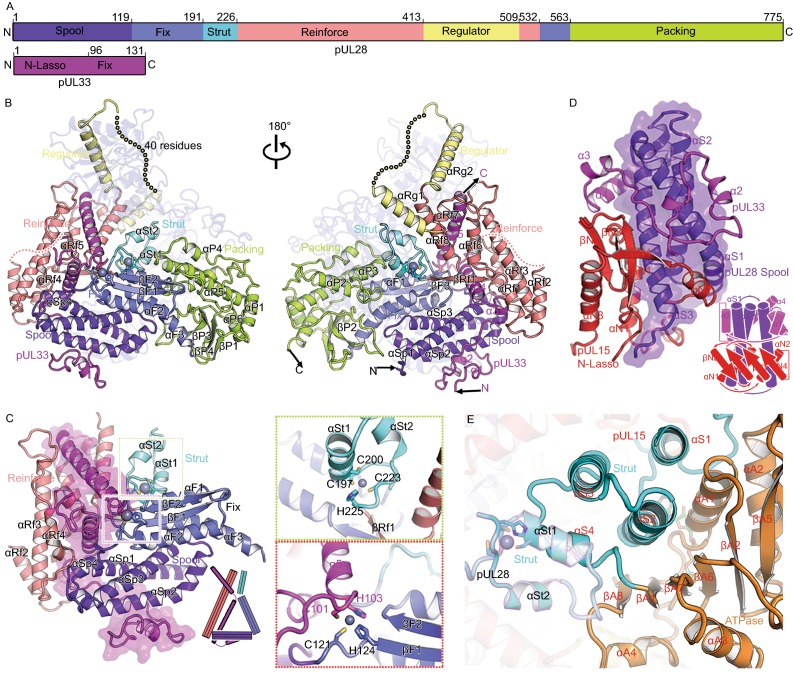
Figure 3.
Structural basis for assembly of the terminase complex. (A) Schematic diagram of domain organization of pUL28 and pUL33. (B) Views of overall structure of the terminase complex. Domains, N terminus, C terminus and secondary structural elements of pUL28 and pUL33 are labeled. Color schemes for pUL28 and pUL33 are the same as Fig. 3A. pUL15 is colored in blue with 70% transparency. Residues 433–477 that are disordered in the structure are labeled as dots. (C) The “thread a needle” interaction mode between pUL33 and pUL28. A model shown at the right-bottom depicts the interaction mode. Insets illustrate two zinc-finger structures. (D) The “spool of wires” assembly mode of three N-terminal domains of the terminase complex. A model shown at the right-bottom depicts the assembly mode. (E) Double fixation of the ATPase by two sets of three-helix bundle from two strut domains. pUL28 and pUL15 are highlighted in magenta and black outlines. Secondary structural elements from pUL15 are labeled in red. (F) The interactions between two adjacent subunits of the hexameric terminase assembly. The packing domain shows tight contacts with the N-lasso, reinforce and strut domains from the neighboring subunit in the black inset. Color scheme is same as in Figs. 2A and 3A. (G) The proposed regulatory re-arrangement of the nuclease using two sets of “regulators” from pUL15 and pUL28. Left: the location of two “regulators” in the hexameric terminase assembly; Right: zoom-in view of two “regulators” within one terminase complex. The regulators from pUL28 and pUL15 are highlighted in magenta and black outlines


