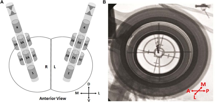
FIGURE 1.
Directional leads and orientations. (A) Schematics showing the 8-contact directional leads in the right and the left hemisphere from the anterior view. Contacts 1 and 4 representing the ring contacts at bottom and top, respectively. The stereotactic marker and directional contacts 2A–3A indicating anterior. Depending on the implantation side (right/left), directional contacts 2B–3B and 2C–3C indicating lateral or medial. (B) An intraoperative fluoroscopy image from P1. The stereotactic marker facing anterior. In order to prevent any confusion, labels “2B–3B” and “2C–3C” were changed to “2M–3M” and/or “2L–3L” directions based on the hemisphere. D, dorsal; V, ventral; M, medial; L, lateral; A, anterior; P, posterior.

