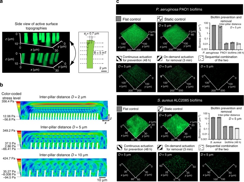
Fig. 3. Optimization of the pillar design.
a Bending of PDMS pillars with a height of 10 µm, diameter of 2 µm, inter-pillar distance of 5 µm, and Young’s modulus of 2.1 MPa in response to a 5 mT magnetic field. The pillars appeared green in fluorescence microscopy after being labeled with Acridine Orange. b Stress propagation in viscoelastic biofilms generated by the on-demand beating of active pillars with different inter-pillar distances (D = 2, 5, and 10 µm). Active pillars (in white color) were actuated using a 5 mT magnetic field. c Representative fluorescence images of biofilms on flat controls, static controls, and PDMS surfaces with active surface topographies. The pillars were 10 µm tall with a diameter of 2 µm and inter-pillar distance of 5 µm. Active surface topographies were operated in three modes, including continuous beating for biofilm prevention, on-demand removal of mature biofilms (only actuated for 3 min after 48 h of biofilm growth), and a sequential combination of these two treatments. Biofilm cells were labeled with STYO®9. The biomass was quantified using COMSTAT59. The samples in the bar graph are indicated with the pattern labels above the corresponding fluorescence images. Each condition was tested with at least three biological replicates (error bar = standard deviation; n = 3–4), and five random images were taken from each sample. Source data of Fig. 3c are provided in the Source Data file.

