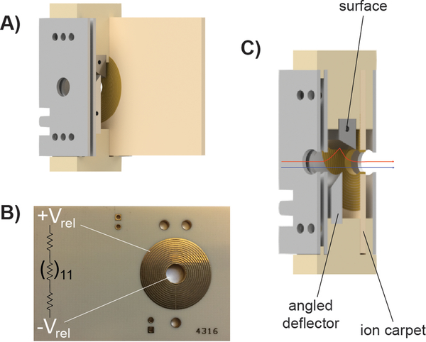
Figure 1.
A) Computer-aided drawing (CAD) of the tilted-surface/ion carpet SID device. B) Image of the ion carpet printed circuit board with a representation of the resistively linked (in series) concentric ring electrodes. C) Technical drawing of the device with a cutaway in which the blue arrow shows the ion path when the device is tuned for transmission/no ion activation. The red arrow indicates a stylized view of the ion path when the device is tuned for surface collision.

