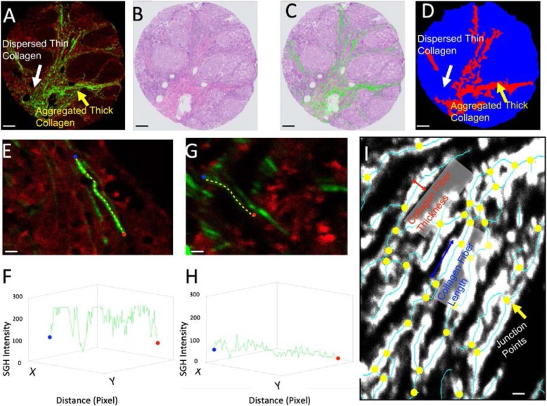
Fig. 1.
TPE/SHG technique and digital collagen structural profiling for TNBC TMA samples. a TPE/SHG image of TNBC TMA. The red channel is the TPE channel of excitation wavelength 780 nm and emission wavelength 560 nm; the green channel is the SHG channel (wavelength 380 nm), known as second harmonic or frequency doubling. SHG is highly sensitive to changes in collagen fibril and fiber structures. b A representative patient TMA sample stained by H&E. One unique advantage of the TPE/SHG imaging technique is that it is stain free. Once the SHG image is acquired, the same sample can be stained with H&E and scanned as a digital image. c The overlay of the collagen structure acquired in SHG and the H&E images. Since a and b are two images of the same physical slide, it is possible to fuse them together. d The differentiation of tissue area occupied by aggregated thick collagen (ATC) and dispersed thin collagen (DTC) based on intensity, texture, and morphology. The red area, as shown by the yellow arrow in a and d, is the ATC area; the blue area, shown by the white arrow in a and d, is the DTC area. The ATC area primarily contains aggregated collagen, and the DTC area contains dispersed collagen. Some parts of the DTC area may contain relatively small collagen compartments. e A brighter collagen fiber and f its SHG intensity reading. g A weaker collagen fiber and h its SHG intensity reading. The measurements are taken starting from the blue dot and ending at the red dot along the path of the yellow dotted line. Collagen fiber density (CFD) is a unique quantitative reading from SHG which indicates the collagen packing structure. i Once the fiber is segmented using the Gaussian mixture model (GMM), the structural information of the collagen can be extracted. The yellow dots are the junction points. It is then possible to measure different features, including CFL, CFT, and CRI. Scale bars: a–d 100 um, e, g, i 2 um

