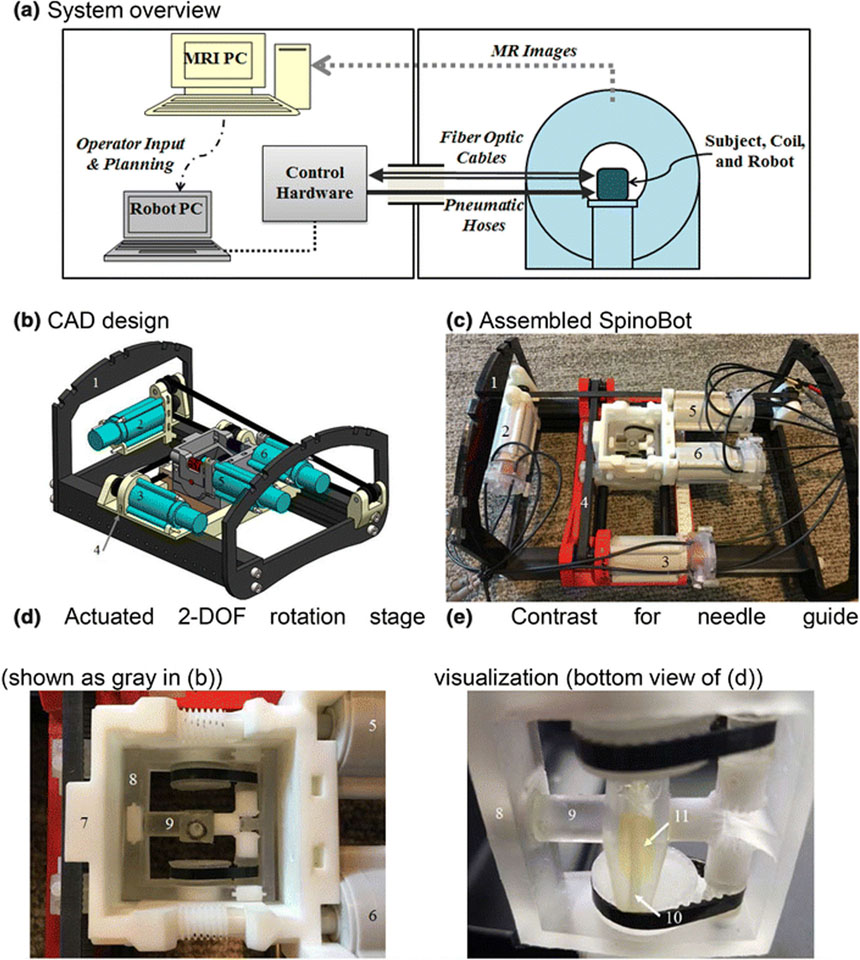
Figure 1.
(a) Block diagram overview of robotic system and its setup in MRI and control rooms. (b) CAD assembly of the 4DOF SpinoBot. (c) The assembled SpinoBot. (d) Close-up of the actuated rotation stage. (e) Close-up of needle guide. The following components are visible in (b) and (c): (1) coil support, (2) x-axis actuator, (3) y-axis actuator; (2) and (3) are connected to (4) translating stage. (d) and (e) show: (5,6) angulation actuators, which are connected to (7) angulation stage. (8) theta (θ) angulation unit allowing rotation in 2 DOF (See Fig. 2 for details), (9) phi (φ) angulation unit. Embedded in (9) is (10) a needle insertion guide containing (11) gadolinium image contrast agent (yellow fluid) for needle guide visualization.

