Figure 1.
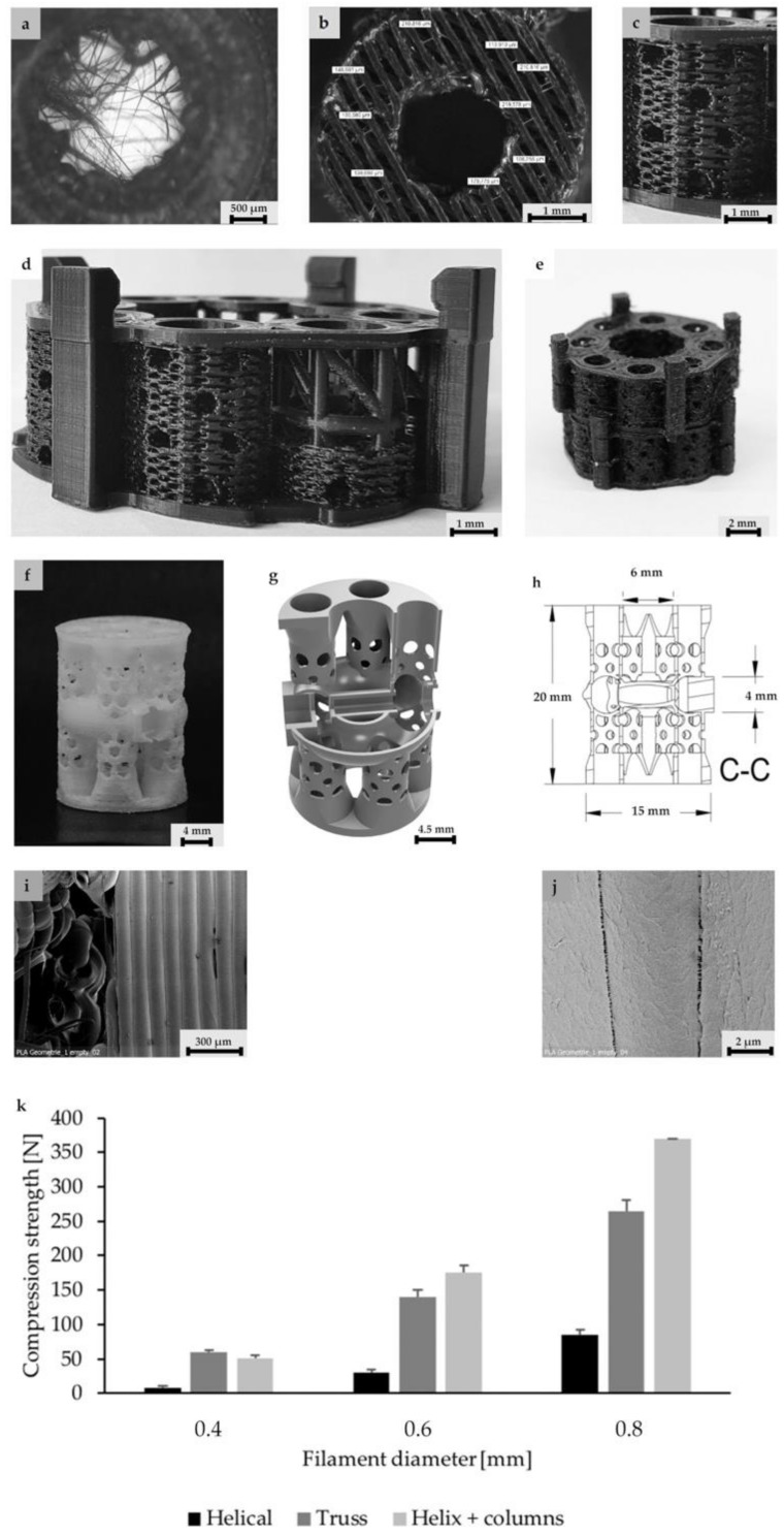
Structure levels in detail (for better illustration of structure details dyed PLA was used here): (a) Close up of a central column. In the center, the filamentary net is visible. Net printing via controlled extrusion, as used for surrounding wall printing, was not possible. Printing parameters had to be adjusted. Flow was decreased and distance between single filaments was increased from 0.1 to 0.3 mm. Althhough filamentary structures are discontinuous, they offer pores in the range of less than 100–150 µm and a high surface/volume ratio. (b) Axial image of single hollow column structure. For better illustration of the wall’s porous fine structure, the solid base ring is missing. (c) Basic unit of this concept: The single column image that inhabits the filamentary nets. The nets are easily accessible through the porous walls varying in diameter. (c,d) Eight hollow columns build up one subunit of the scaffold. At the bottom and top, base rings provide stability for a smooth force transduction. Additionally, the ring is the origin for filamentary Level 2 structures, shown in (a). (c,d) Subunits can be combined via an outsourced clamp system. The rigid truss-like structures were covered with porous walls, to ensure porosity in the range of 300–1500 µm. (f) 3D-printed design alternative: Design 2. (g) A highly porous structure with a central vertical and horizontal channel as well as four rotationally symmetric hollow cylinders. The structure consisted of columns functioning as subunits, which were combined by means of a small pedestal with a ring on the bottom and the top. (h) Dimensions of the second design. (i,j) Microstructures of untreated PLA scaffolds in SEM. Intercolumn areas of the filaments offer narrow spaces (i) and tight cooling cracks (j). (k) Verification of the axial compressive strength of three structural designs and characteristic diameter of struts vs. compressive strength. Test were performed with single hollow columns (diameter: 5 mm; height: 5 mm) (c). Finally, a compromise between strength and material volume was chosen. Experiments were carried out only once for verification of the design. In the future, a validation of the structure with the final design must be carried out. To adapt a scaffold to the size of a critical size bone defect, any number of hollow columns can subsequently be combined on a common base plate. The load is then distributed evenly.

