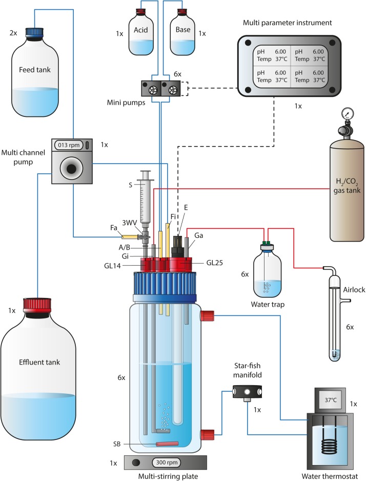
FIGURE 1.
Flow chart of a single bioreactor operated in the MBS. The 1-L bioreactor vessel consisted of a double-walled glass vessel and a customized lid, while it was placed on a multi-stirring plate with up to six bioreactors. The bioreactor temperature was maintained through a water circulation unit at 37°C. The autoclavable lid offered connections for 5x GL14 and 1x GL25. A set of stainless-steel tubing was used for the gas-in/-out lines and for the medium feed-out line. The three-way valve at the medium feed-out line was required for sampling using a 5-mL syringe. The pH and bioreactor medium temperature was tracked via a pH/pt1000-electrode that was connected to a multi-parameter instrument. The multi-parameter instrument controlled and triggered two mini pumps (for base and acid) at programmable conditions. For continuous mode, the feed medium to each bioreactor was pumped via a single multi-channel pump from the feed tank into the bioreactor. The same pump was used to transfer the effluent from each bioreactor into the effluent tank. Sterile CO2 and H2 gas (20:80 vol-%) was sparged into the system through stainless-steel tubing with an attached sparger. The gas-out line was connected to a 100-mL serum bottle to serve as a water trap before the outgoing gas passed an airlock. The 1×, 2×, and 6× next to each unit in the figure describe the quantity, which is required to operate six bioreactors simultaneously. A/B, Acid and/or base feed line; E, pH/pt1000 electrode; Fa, medium feed-out line; Fi, medium feed-in line; Ga, gas-out line; Gi, gas-in line; GL14, screw joint connection size 14; GL25, screw joint connection size 25; rpm, revolutions per minute; SB, stirring bar; 3WV, three-way valve. Blue lines indicate liquid transfer, red lines contain gas, and dotted black lines provide electric power or signals.

