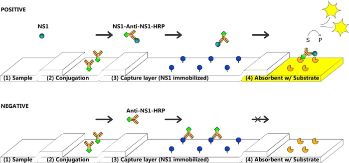
Figure 1.
Schematic presentation of the capture flow assay biosensor. It consists of membranes with specific applications for each. (1) Pad for the collection of a liquid sample. (2) Pad with an antianalyte bioreporter molecule linked to some marker. (3) Blocking pad, with preimmobilized analyte. (4) Measuring pad with a specific substrate. There are two main possibilities that can happen during measurements. In the first test (upper), the sample with a target analyte (NS1), after deposition on the pad (1), will be connected to bioreporter molecules (in this case, antibodies–HRP attached). The complex will then migrate inertly through a pad (3) and reach pad (4) to produce a measured signal since the complex is already formed. The sample without the target analyte (lower) will migrate from the pad (2) and then move unbound antibodies (in this case) to the capture layer (3), where they will be linked to the preimmobilized analyte and stopped from migrating to the next pad. Thus, no visible signal will be observed.

