
Figure 3. Design of individual microprobes and the reticle.
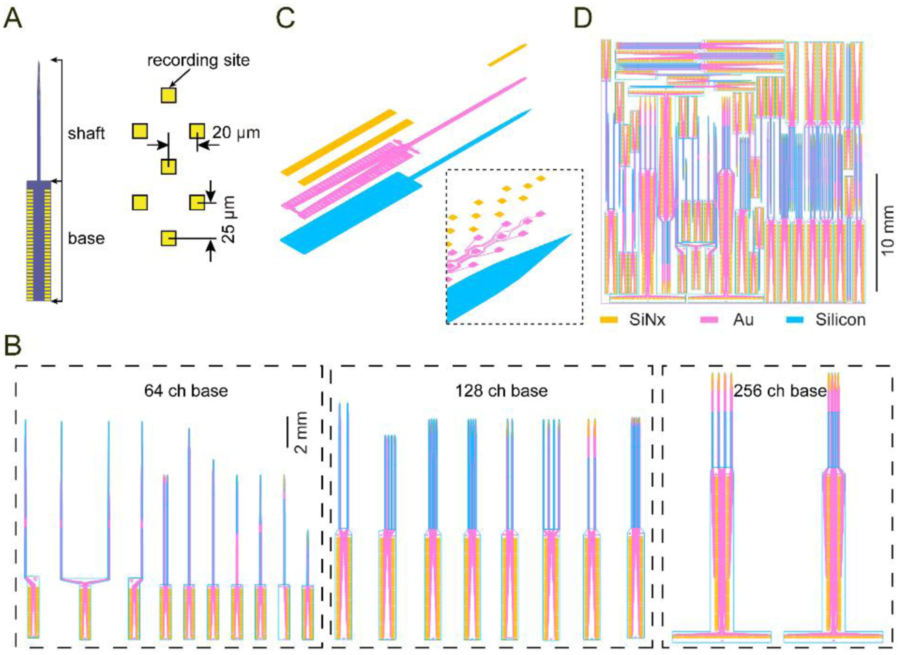
(A) A 64 ch microprobe (64D short) illustrating the shaft and base sections, and the honeycomb electrode layout.
(B) Assortment of different microprobe designs grouped by base section (64, 128, or 256 ch).
(C) Expanded view of the three structural layers used for microfabrication (orange: silicon nitride window for exposing the electrodes and wire bond contact pads; magenta: metal layer comprising the electrodes, interconnecting wires, and wire bond contact pads; blue: silicon microprobe 2D profile). The inset shows a closeup of the probe tip.
(D) Reticle layout containing an assortment of individual devices arranged closely together to minimize empty space.