
Figure 5. PCB design, device assembly, and micromanipulator holders.
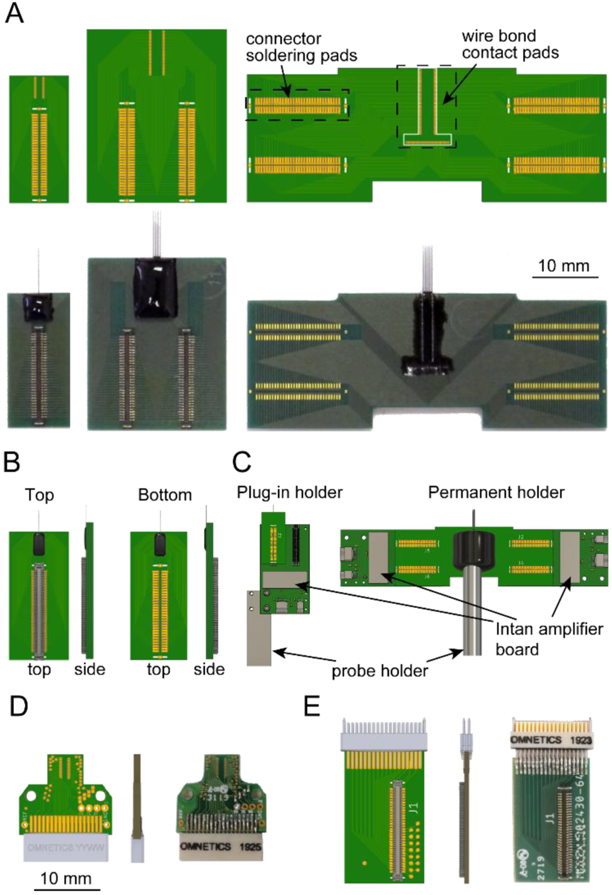
(A) Top: three standard PCB designs. The connector solder pads connect to a Molex Slimstack connector (part # 5024306410). Bottom: images of the corresponding PCBs after assembly and epoxy encapsulation. Note that the connectors on the lower right device are assembled in the bottom mode.
(B) Illustration of the top and bottom connector assembly modes.
(C) Illustration of the plug-in and permanent holders. The drawing of the 128 ch amplifier board was downloaded from www.intantech.com.
(D) 32 ch PCB with Omnetics connector for freely moving animal recordings.
(E) Omnetics-to-Molex connector adapter for the 32 ch PCB in (D).