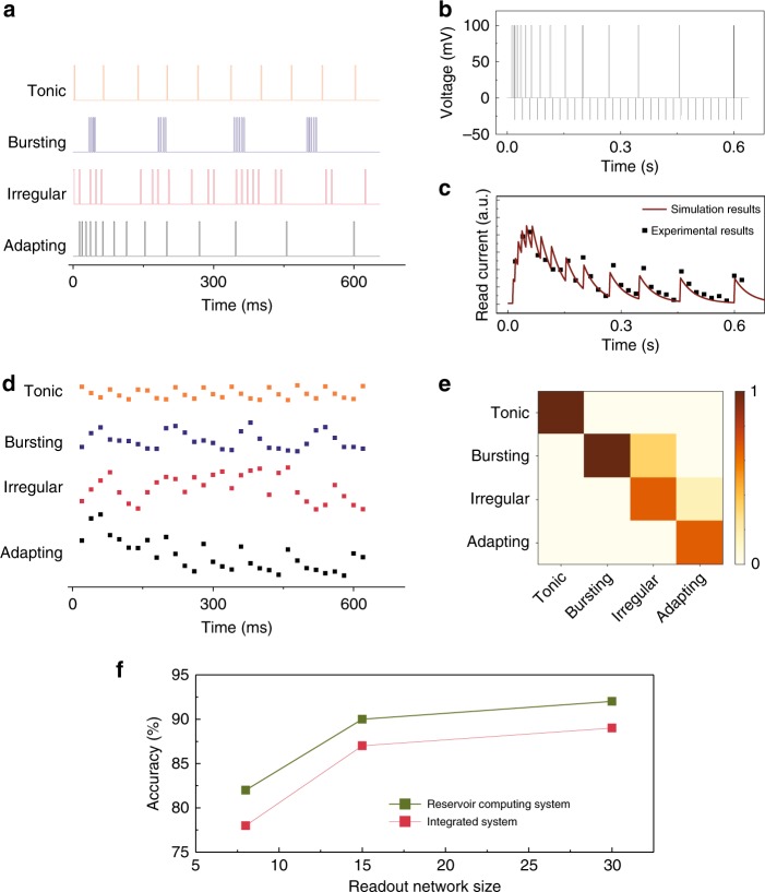
Fig. 3. Neural firing pattern recognition.
a Typical spike trains corresponding to four common neural firing patterns. b Waveform of a spike train applied to the memristor during the measurements, including spike inputs (the “Adapting” pattern in this example) and the read pulses (−30 mV, 0.5 ms, with an interval of 20 ms). c Evolution of the read current (black dots) measured from the device when excited by the spike train in b. The experimental results agree well with the simulation results (solid curve) based on a dynamic memristor model15,20. d Evolution of the memristor read current for the spike trains shown in a. e False color confusion map showing the experimentally obtained recognition results. The occurrence probability for each firing pattern is represented by the colors shown in the color scale. f Simulated neural firing pattern recognition accuracy at different readout layer sizes, for the integrated system that integrates the input data over a fixed time period, and the memristor-based reservoir system.

