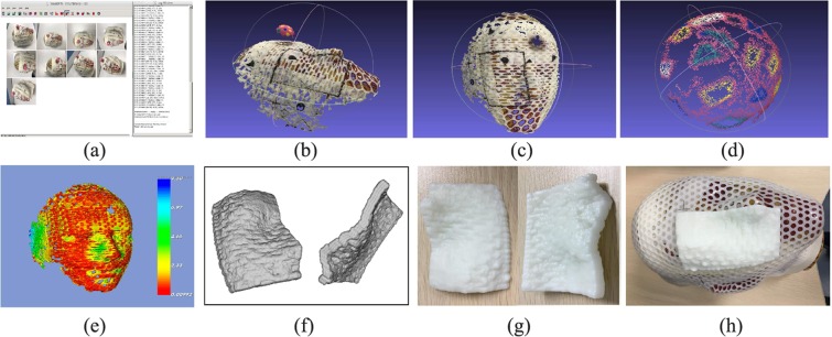
Figure 1.
Procedure of bolus reconstruction using the SFM method. (a) The acquired pictures were imported into SFM workspace and 3D reconstruction was run. (b) The surface of the head phantom and the sphere calibration model. (c) The surface of head phantom with a bolus region marker line. (d) The surface of the sphere calibration model. (e) The registration deviation between the two surfaces from the SFM and Marching Cube from CT images. (f) Bolus viewed in the STL format file. (g) The bolus printed using ABS material. (h) The bolus was put in the right place on the head phantom surface.

