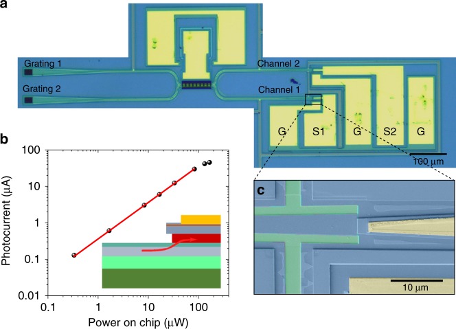
Fig. 3. Integrated sensor and response of the photodiode.
a Optical microscope image of the integrated displacement sensor. G stands for ground, S1 and S2 stand for signal of channel 1 and channel 2. b Photocurrent measured on a waveguide photodiode connected directly with a grating coupler at 1540 nm as a function of power on chip. Linear fit of the photocurrent with power under 100 µW is indicated by red line. Inset: Schematic of the integrated photodiode. Red arrow marks the direction of incoming light. c SEM image of the integrated photodiode in false colors.

