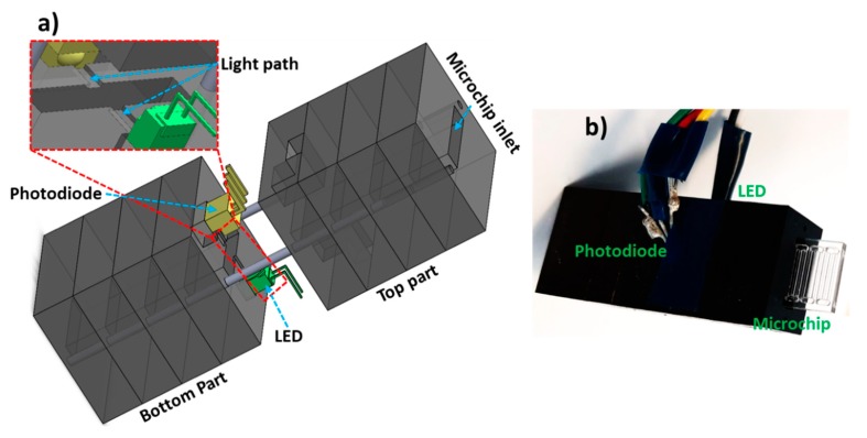
Figure 1.
Optical flow cell overview. (a) Schematic of the portable flow cell illustrating LED, photodiode, light path and microchip inlet. (b) Photograph of the flow cell with a microchip inserted into the inlet. Multiple PMMA pieces (5 mm thickness) were micromilled and combined via alignment pins. Bottom par houses the LED and photodiode while the top part allows the electrical connections to the microcontroller.

