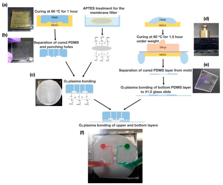
Figure 2.
Fabrication of our flow-free microfluidic device. (a) Pre-cured PDMS was poured into 3D printed molds. (b) After curing, the top PDMS layer was separated from the mold, and inlet and outlet holes were punched. (c) A polycarbonate membrane was bonded to the top PDMS layer through O2 plasma bonding after 3-aminopropyltriethoxysilane (APTES) treatment. (d) A weight was placed on top of the pre-cured PDMS during the curing process to create a thin PDMS layer with the gradient chambers. (e) Image of the bottom PDMS layer with hollow gradient chambers after being separated from the mold. (f) Functional flow-free microfluidic device with green and red dye in water for flow visualization.

