Figure 2.
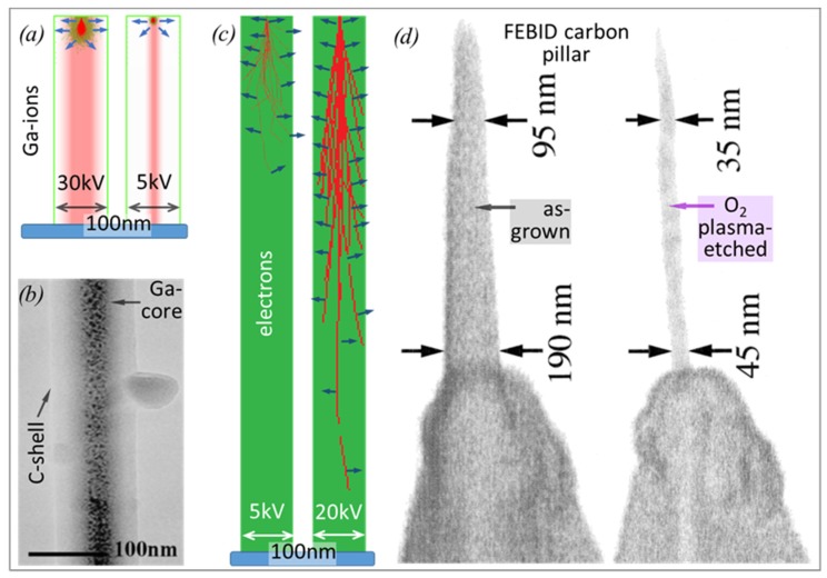
(a) SRIM (stopping and ranges of ion in matter) [15] simulation of a zero-diameter gallium ion beam and 100 trajectories (red) with the adjacent collision cascade (green) in a 100 nm wide and 400 nm tall pillar of carbon (density 2 g/cm3) illustrating the inevitable implantation of Ga (shaded red) and its redistribution via the collision cascade for primary energies of 30 kV (left) and 5 kV (right). Blue arrows signify secondary electrons (SEs), leading to deposition events if generated in close proximity to the surface. (b) TEM image of a core–shell structure of an as-grown Ga-based, FIBID carbon pillar using phenanthrene. Modified from Matsui et al. [69]. (c) CASINO [66] simulation of a zero-diameter electron beam and 20 trajectories (red) in a 100 nm wide and 1 μm tall carbon pillar for primary electron energies of 5 keV (left) and 20 keV (right). The electron trajectories were truncated once they exit the pillar volume for the sake of clarity. Blue arrows again indicate SEs generated along the electron paths. (d) SEM side view images of a carbonaceous FEBID pillar deposited from residual vacuum pump oil molecules on an AFM tip before (left) and after oxygen plasma treatment (right). The much narrower core that remains indicates a different chemical bonding, which is closely related to different mechanical properties. Modified from Wendel et al. [68]. Note that (a) and (c) have the same scale for easy comparison and that the pillar diameters will also depend on the charged particle beam intensity profile (focus), which was omitted for the sake of clarity.

