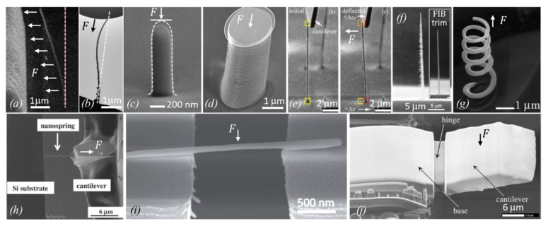
Figure 13.
Overview of published metal–carbon deposit shapes and methods to determine their elastic moduli. The force F acting on the structure is indicated as well as the initial shape of the structure (dashed line). (a) Pt-C FEBID pillar bent within an electrostatic field toward the electrode, modified from Arnold et al. [47]. (b) Buckled Pt-C pillar between an actuator (top) and substrate (bottom). The initial shape was straight as indicated, modified from Hao et al. [90]. (c) Pt-C FEBID pillar nanocompression by a flat diamond punch (not shown), modified from Lewis et al. [48]. (d) FEBID Co-C pillar with Ga–FIB milled flat top for compression experiments. (e) Cu–C pillar bending with cantilever and pillar base image tracing, modified from Friedli et al. [53]. (f) FIB pillar from W(CO)6 giving large lateral spike shapes (left), which were FIB-milled for better shape assignment in bending experiments, modified from Ishida et al. [100]. (g) FIB grown helix with W(CO)6 and C14H10 for tensile strain experiments, modified from Nakamatsu et al. [43]. (h) Tensile strain experiment with Fe-C FIB helix fixed between a cantilever and substrate, modified from Nakai et al. [59]. (i) FIB W-C horizontal rod three-point bending experiments, modified from Córdoba et al. [51]. (j) FIB grown silicon oxide structure with FIB-milled hinge geometry for bending experiments, modified from Reyntjens et al. [62].

