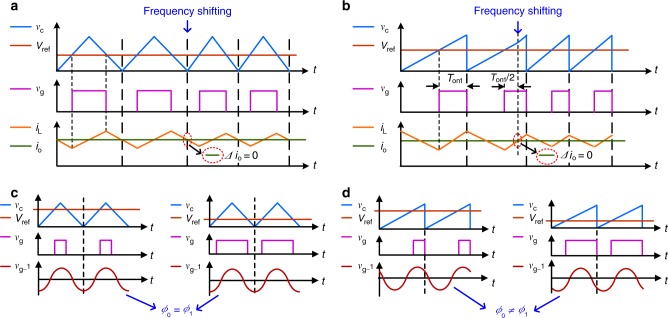
Fig. 4. Comparison of two different carriers of a triangle wave and a sawtooth wave.
a A triangle wave sequence is adopted to generate the PWM sequence. The top waveforms, vC and Vref, are the triangle wave and the dc reference signal, respectively. The middle waveform, vg, is the generated PWM sequence, i.e., the gate signal. The bottom waveforms, iL and io, are the inductor and output currents, respectively. At the moment of the frequency shift at the peak of the triangle wave, the output current remains stable (Δio = 0). b A sawtooth wave sequence is adopted to generate the PWM sequence. The top waveforms, vC and Vref, are the sawtooth wave and the dc reference signal, respectively. The middle waveform, vg, is the generated PWM sequence, i.e. the gate signal. The bottom waveforms, iL and io, are the inductor and output currents, respectively. At the moment of the frequency shift, the output current remains stable (Δio = 0). The frequency shift occurs on the upward ramp of the sawtooth wave, where the high level of vg lasts for ½Ton1. c A triangle wave sequence is adopted to generate the PWM sequence. The top waveforms, vC and Vref, are the triangle wave and the dc reference signal, respectively. The middle waveform, vg, is the generated PWM sequence, i.e. the gate signal. The bottom waveform, vg_1, is the fundamental component of the gate signal. When the duty cycle of the gate signal changes, the phase of vg_1 remains constant. d A sawtooth wave sequence is adopted to generate the PWM sequence. The top waveforms, vC and Vref, are the sawtooth wave and the dc reference signal, respectively. The middle waveform, vg, is the generated PWM sequence, i.e. the gate signal. The bottom waveform, vg_1, is the fundamental component of the gate signal. Φ0 and Φ1 refer to the phase of before and after the duty cycle changes. The phase of vg_1 varies with a change in the duty cycle.

