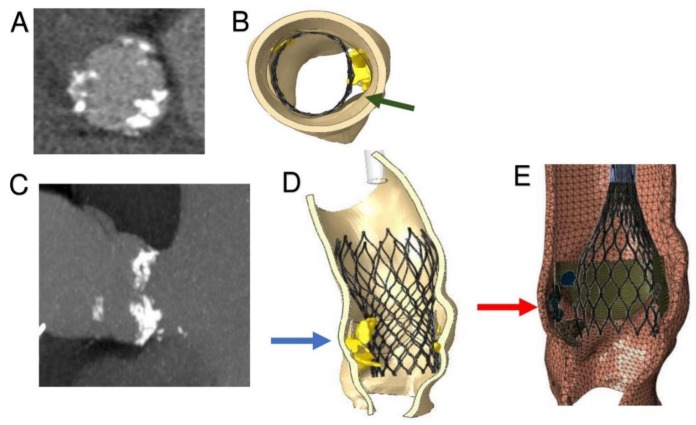
Figure 4.
Inclusion of calcific blocks and Finite Element Analysis simulation of TAVR procedure. (A) CT image, aortic valve from transverse plane: leaflet calcifications. (B) Top view of patient-specific 3D aortic root reconstruction: calcifications attached to the leaflets. Persistent bulky calcifications may determine the development of paravalvular leakage. (C) Influence of bulky calcification on device biomechanical behavior. (D) Simulation of stent self-expansion after catheter removal: lack of prosthetic anchorage corresponding to uncrushed calcific plaques (blue arrow). (E) Great calcification prevents good left ventricular outflow tract (LVTO) inferior placement of CoreValve (26 mm) and upward stent migration (red arrow).

