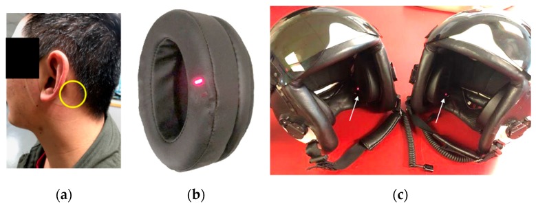
Figure 1.
(a) Photograph of a test subject after removing helmet instrumented with SPYDR earcups. The yellow circle indicates optimal anatomical placement of the SPYDR sensor when worn. (b) Photograph of the SPYDR ear-cup. The multi-wavelength plethysmography sensor is seen as the red light embedded in the ear-seal. (c) Photograph of Navy flight helmets HGU-68, configured for tests with SPYDR installed. The white arrow indicates the red light of the sensor.

