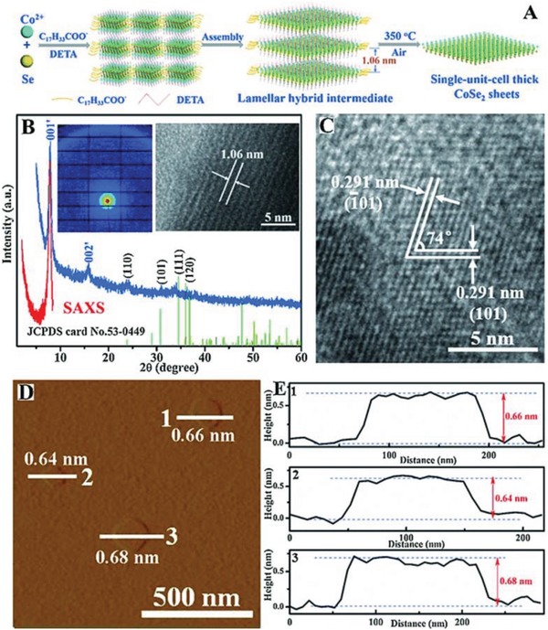
Figure 12.

A) Schematic illustration for fabricating thick orthorhombic phase CoSe2 sheets. B) SAXS profile (red line and inset left image), XRD pattern (blue line) and the corresponding lateral TEM image for the lamellar hybrid CoSe2‐DETA intermediate. C) HRTEM image of the thick orthorhombic phase CoSe2 sheets. D) AFM image and E) the corresponding height profiles for the thick orthorhombic phase CoSe2 sheets. Reproduced with permission.254 Copyright 2015, Wiley‐VCH.
