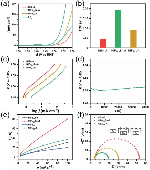
Figure 4.

a) Polarization curves of NiSn‐A, NiFe0.5Sn‐A, NiFe0.5‐A, and Ir/C. b) bar chart for a comparison of TOF of NiSn‐A, NiFe0.5Sn‐A, NiFe0.5‐A. c) Tafel plots of NiSn‐A, NiFe0.5Sn‐A, and NiFe0.5‐A. d) chronopotentiometry plot of NiFe0.5Sn‐A. e) Cdl calculations of NiFe0.5Sn and NiFe0.5 before and after anodization. f) Nyquist plots of NiSn‐A, NiFe0.5Sn‐A, NiFe0.5‐A at 1.53 V. The inset two‐time constant circuit consists of a solution resistance (R s), two constant phase elements (CPE), a resistance related to surface porosity (R p) and a charge‐transfer resistance (R ct).
