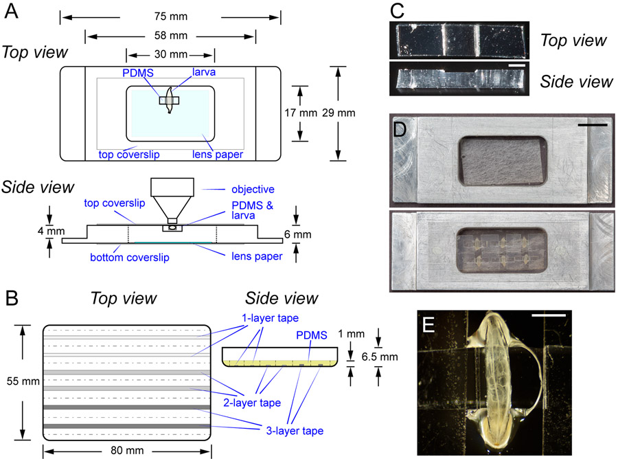
Figure 1: The imaging chamber for LarvaSPA mounting.
(A) Diagrams of the imaging chamber with detailed specifications, showing both the top view and the side view. The light blue shading in the top view indicates the moistened lens paper. The chamber is sealed by a top coverslip and a bottom coverslip. The position of a mounted larva is illustrated. (B) Diagrams of the PDMS mold (the top view) and the mold after filling with the PDMS mixture (side view). Strips in grey indicate two 1-layer, two 2-layer, and two 3-layer tape strips, respectively. The yellow shading in the side view indicates the PDMS mixture in the mold. The dotted lines indicate where to cut the cured PDMS. The side view of the diagram is not drawn to scale. (C) Photographs showing a top view and a side view of a PDMS cuboid. Scale bar = 1 mm. (D) Photographs showing an imaging chamber before mounting, and an imaging chamber with six immobilized late third instar Drosophila larvae mounted dorsal side up. Scale bar = 10 mm. (E) A closer view of a larva in (D). Scale bar = 1 mm.

