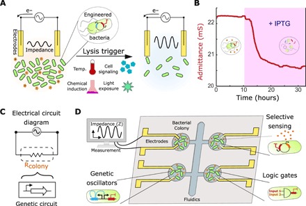
Fig. 1. Interfacing genetic circuits with electrical measurement.

(A) Schematic of the approach using a culture of bacteria with a killing gene as the circuit output in contact with inert gold electrodes. The impedance of the culture reduces during growth (left) and increases upon the induction of bacterial death due to the clearance of charged metabolites (right). (B) Profile of the admittance (red), which is the inverse of impedance, using an IPTG-inducible lysis construct (pE35GFP) (42) in an electrochemostat device. The pink shaded region represents induction of lysis with 1 mM IPTG in the medium. (C) Schematic of the equivalent electrical circuit for our strategy using an alternating input voltage. The bacterial population is simplified to a resistor, which is controlled by a genetic circuit. (D) Schematic showing a microelectronic platform to interface between engineered bacteria and electronics. Several chambers may contain unique genetic circuits, connected via electrodes to an impedance output system.
