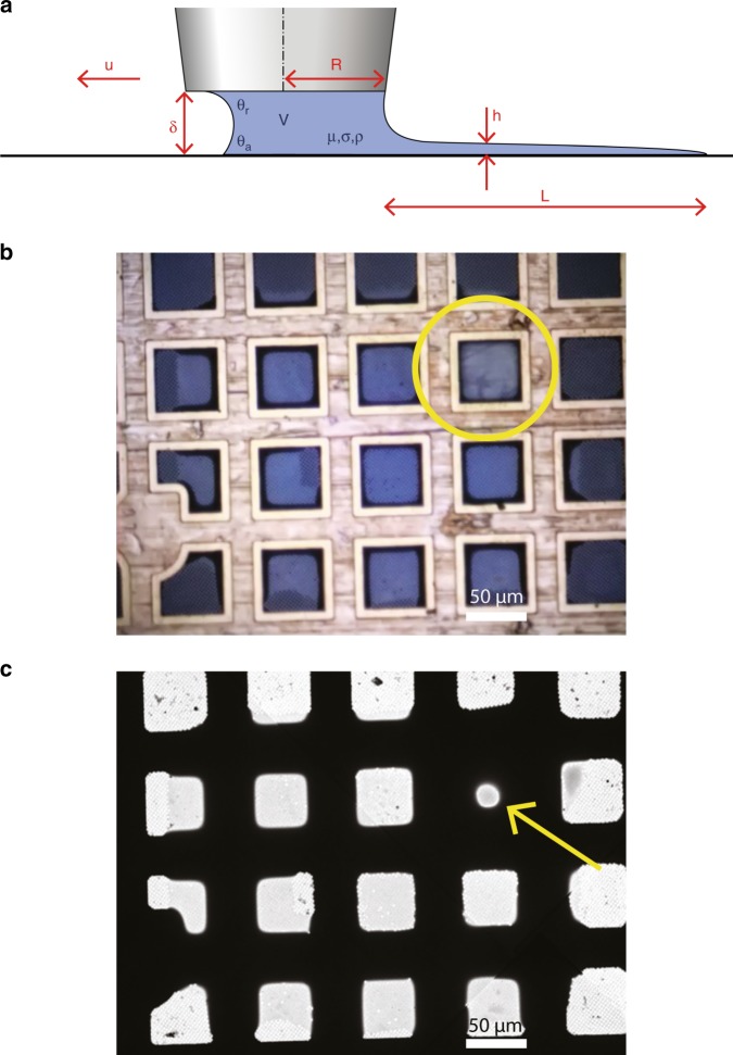
Fig. 2. Pin-printing parameters and resulting sample deposition.
a Schematic overview of relevant parameters for pin printing. The deposited layer in height (h) and length (L) is a result of the sample properties (viscosity μ, surface tension σ, density ρ), contact angles (advancing at the grid θa, receding at the pin θr), and writing parameters (standoff distance δ, pin radius R, pin velocity u). b Photograph of the grid by the integrated camera shows the sample applied by pin printing. The pin is indicated by a yellow circle. c Low magnification cryo-EM atlas of the deposited and vitrified sample. One thicker square (arrow) is the result of retraction of the pin from the grid. Scale bars represent 50 μm.

