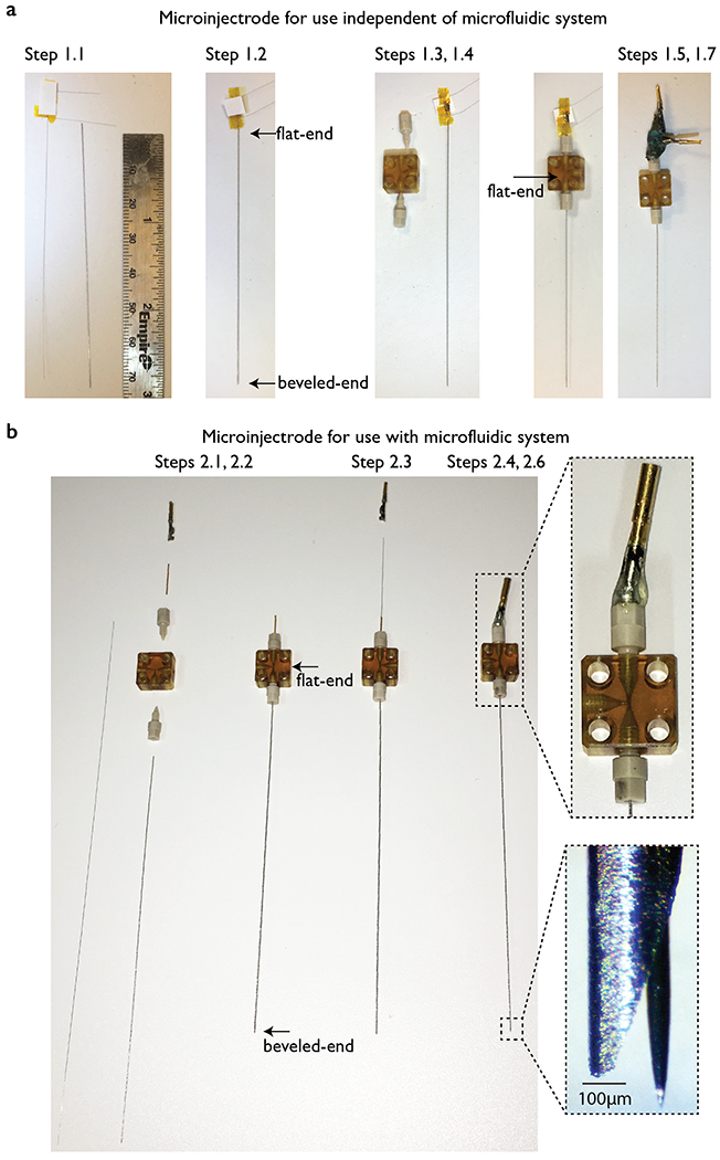
Figure 1. Step by step fabrication of microinjectrode.

(a) Configuration for use independent of microfluidic system. Cannula and probe are measured in order to confirm that the tip of the probe can be protruded at the desired length (e.g., 150 μm). The probe is front loaded into the cannula. The cannula is passed through the T-junction and attached on the bottom side, with the flat end in the middle of the T-junction; the back end of the probe continues through the top ferrule. The microinjectrode is finalized by soldering gold pins on each of the probe terminals and adding glue between them and the top ferrule for stability. Connection to the acquisition system depends upon the design of the probe. In this example, our probe is a nanosensor with three leads. (b) Configuration for use with microfluidic system. To couple the microinjectrode to the microfluidic system, a piece of capillary tubing is used for the top side of the T-junction. The probe can be front or back loaded. The microfluidic line is then plugged to the third T-junction opening. In this example we used a microelectrode. See the zoomed picture of the tip of a cannula in which the microelectrode was protruded by tightening the top ferrule. See the Table of Materials for a list of items used in construction.
