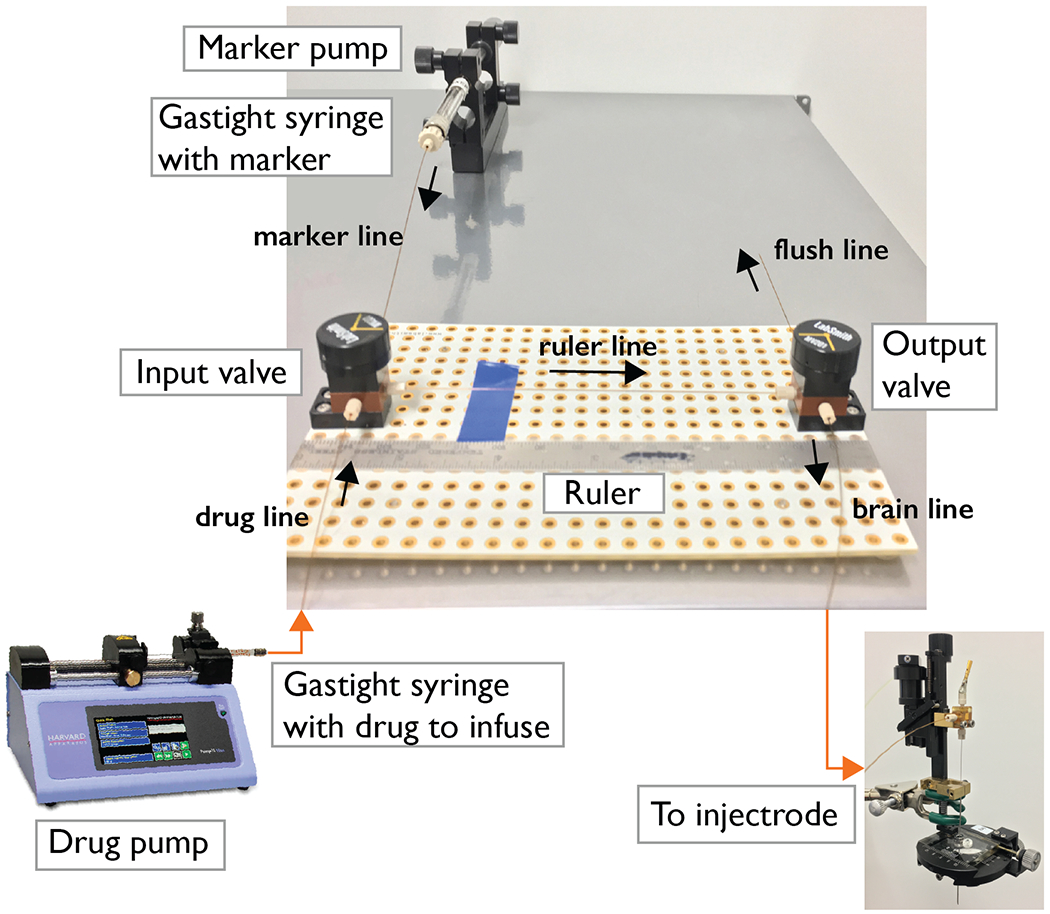
Figure 2. Microfluidic system.

The two-valve configuration allows control of flow direction towards the microinjectrode or towards the flushing line for troubleshooting. The circuit relies on two 3-port valves connected using capillary tubing and standard ferrules. Gastight syringes are used to carry and inject the infusion drug and the marker. A programmable syringe pump allows for automatic flushing of the system and loading of the drug. A manual microsyringe pump allows for controlled injection and visualization.
