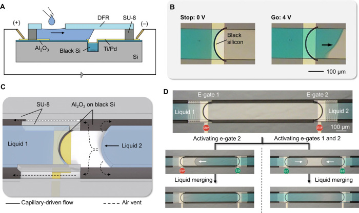
Fig. 6. Self-vented channels and e-gates.

(A) Side view of the components for electrogating using a black silicon area instead of a trench for the implementation of e-gates. (B) Microscope images showing the stop-and-go control of the liquid flow. (C) Three-dimensional (3D)–rendered illustration showing liquid 1 pinned at the e-gate and liquid 2 merging to liquid 1 without creating an air bubble owing to side air vents patterned in black silicon. (D) Examples of merging two liquids stopped at the e-gates (upper frame): Microscope images on the left show bubble-free merging after e-gate for liquid 2 was activated, and the ones on the right show a case where both e-gates were activated at the same time using a common electrode (from movie S8). Photo credit: Yulieth Arango, IBM Research–Zurich.
