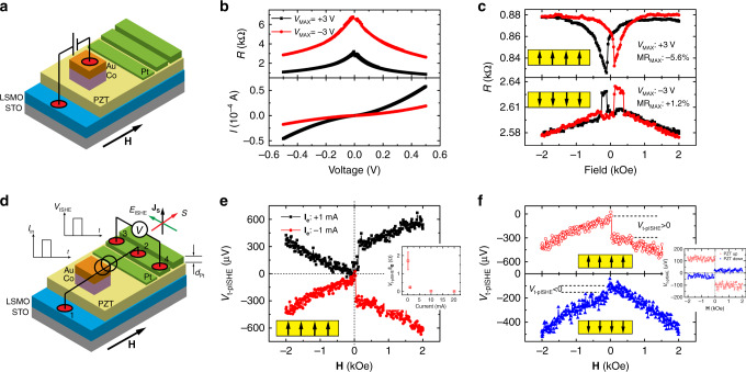
Fig. 2. Ferroelectric control of spin transport in MFTJ and ISHE devices.
a Schematic structure of the LSMO/PZT/Co (MFTJ-type device). b I(V) and R(V) curves of the MFTJ-type device with the polarization of PZT switched by VMAX = +3.0 V (black squares) and −3.0 V (red circles), corresponding to PZT polarized up and down, respectively. c TMR loops of MFTJs measured at VMR = −0.5 V for PZT polarized up (top panel) and down (bottom panel), showing a negative and positive TMR response, respectively. The inserted diagram in each panel stands for the ferroelectric states of the PZT layer. d Schematic illustrations of tunneling pulsed ISHE measurements in the ISHE-type device on the same substrate with the MFTJ-type device. The injected pulsed tunneling current (Ie) generates a flow of pulsed spin current (JS) in the Pt metal, which produces a transverse pulsed ISHE voltage (Vt-pISHE). e typical measured Vt-pISHE(H) plots at Ie = ±1 mA in one ISHE-type device with as-grown PZT film (5 nm thickness, polarization pointing up), respectively. The magnetic field is swept from negative to positive field. The inset shows the measured V t-pISHE/Ie as a function of current. The error bars represent the standard deviation obtained from three different measurements. f The raw Vt-pISHE(H) response (Ie = −1 mA) at two polarization states of PZT layer. The inset figure shows the response after subtracting the symmetric AMR response. The reversed voltage jumps around H = 40 Oe indicates a reversed ISHE response in the Pt metal. All the measurements were taken at 10 K, and the current density is ~10 Acm−2.

