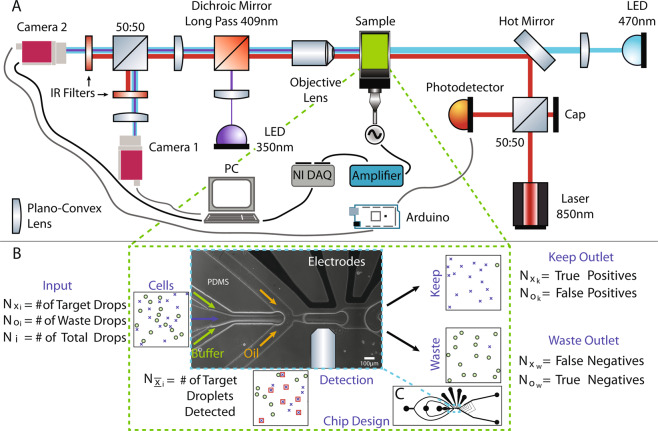
Figure 1.
(A) Custom dual-imaging microscopy system schematic showing laser droplet detection components, and peripheral automation equipment. (B) Illustrative populations at the input (Cells), Detection zone, Keep and Waste outlets to define cell sorting performance parameters. Phase-contrast image of the microfluidic chip (channel borders are white) showing three inlets, the Y-junction and the electrodes for dielectrophoretic sorting. The width of the channel where detection takes place is 83 μm. (C) Complete chip design is shown with three inlets to the left and two outlets to the right. The 4 ports at the top are for the electrodes.

