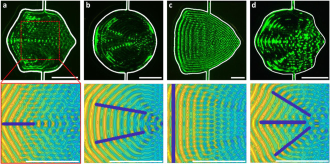
Figure 4.
Implementation of designed channel shapes. Top image row shows patterns of suspended 1 µm polystyrene particles in different channel shapes (interior boundary highlighted in white). The applied surface acoustic wave (SAW) propagates from left to right. The bottom row shows the modeled acoustic field within the design area, 300 × 300 µm for (a,b,d) and 600 × 600 µm (c). These shapes are designed to produce (a) a single focusing region, (b) two focusing regions, (c) a uniform line of particles and (d) three focusing regions. Scale bars are 200 µm.

