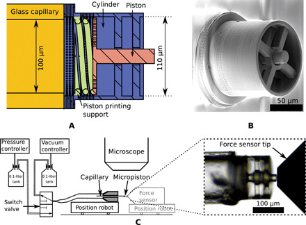
Fig. 3. Micropiston fabrication and setup.

(A) Cross-sectional view of the micropiston design. (B) SEM image of the piston printed by 2PP directly on the tip of a glass capillary. (C) Pneumatic circuit and imaging setup for the proposed micropiston actuation. The figure displays the two possible configurations: one to study the displacement of the piston and the other to study the corresponding force.
