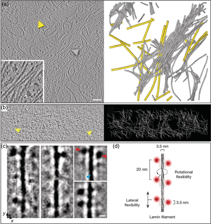
FIGURE 7.

Organization of intermediate filaments (IFs) explored by cryo‐electron tomography. (a) Slice through a tomogram acquired in a focused ion beam‐milled interphase HeLa cell with the Volta phase plate. Inset: Close up on a bundle of smooth cytoplasmic IFs. Arrowheads indicate a microtubule (yellow) and an IF (grey). Cytoskeletal filaments were segmented and displayed using the same color code on the right panel. (b) Slice through the lamina of an interphase HeLa cell. Yellow arrowheads indicate lamin filaments. Three‐dimensional network of lamins are represented in white on the right panel. Reproduced with permission from reference [10], copyright (2016) AAAS. (c) Classes of lamin filaments obtained in vimentin‐null MEFs showing repetitive globular domains spaced 20 nm apart along the filament. Scale bar: 5 nm. Reproduced with permission from reference [180], copyright (2017) Springer Nature. (d) Structural model of lamin filaments. Reproduced with permission from reference [180], copyright (2017) Springer Nature
