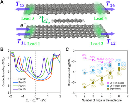
Fig. 3. Theoretical simulations for the charge transport in the graphene M-2D-vdWHs.

(A) Schematic of the graphene M-2D-vdWHs, where PAH 3 is sandwiched between two graphene sheets, used in the calculations. Electrons are injected from lead 1. T11 is the reflection coefficient, while T12, T13, and T14 are transmission coefficients into the other three terminals. (B) Boltzmann-weighted average conductances collected from the gray curves of fig. S14 as a function of the Fermi level relative to that predicted by density functional theory (DFT). The Fermi energy is depicted by the gray vertical dashed line, which is estimated by DFT. Those average conductances are calculated on the basis of binding energies and derived from transmission functions (obtained from the sum of the transmission coefficients T13 + T14) by eqs. S1 to S6 of section S6. The results of linear PAHs are displayed for a tidy and clear view, while those of all the PAHs are shown in fig. S14. (C) Conductances at Fermi energy from DFT calculations and those from the experiment. The brown dots show the experimental values, while the light blue dots represent the theoretical results for graphene M-2D-vdWHs junctions. The magenta is the conductance of linear PAHs in gold-gold break junctions with in-plane transport (fig. S16).
