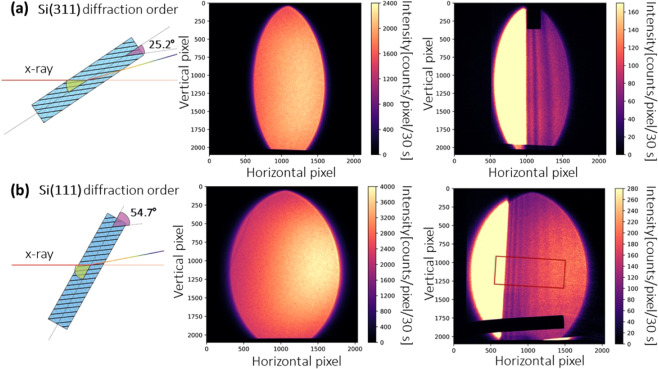
Figure 3.
(a) The Si(311) and (b) Si(111) diffracted Laue beams with a 50 μm Ag foil in the beam. The diffraction order can be switched by simply rotating the Laue crystal. The total energy gradient range corresponds to the colored regions in the inset of Fig. 2b. The CCD camera can cover the whole Laue diffracted beam, which has an elliptical shape with an energy gradient encoded along the horizontal direction and spatial information at same energy encoded along the vertical direction. A strongly absorbing metal bar (Ø = 1.5 mm) was fixed together with the sample for alignment. The non-parallel absorption fringes are due to non-ideal bending of the crystal.

