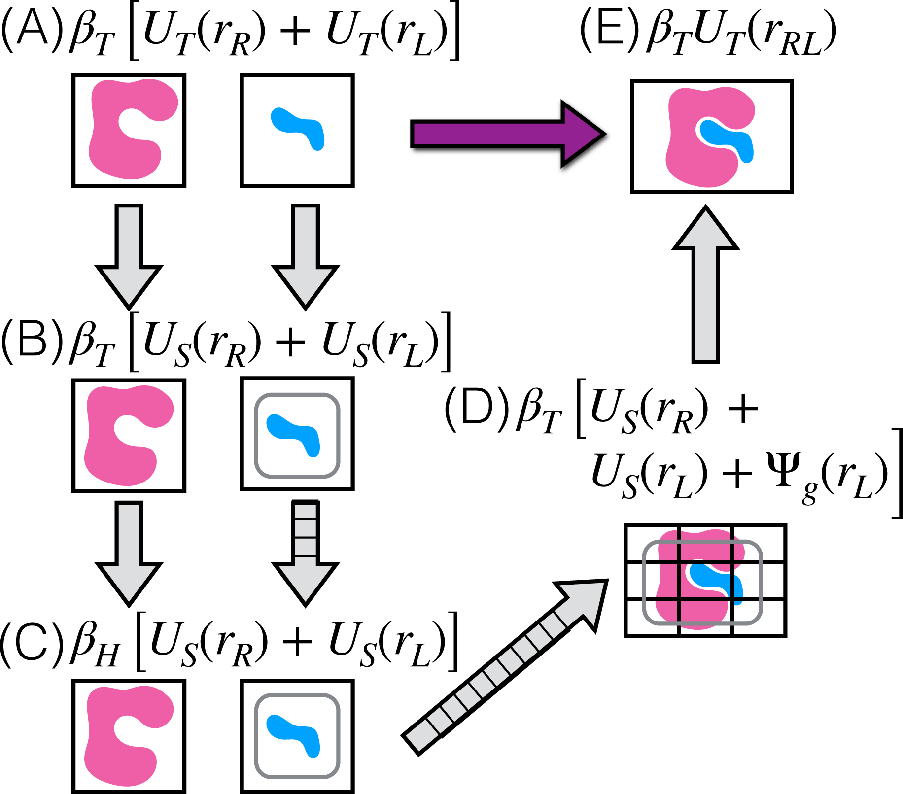
Figure 1: Thermodynamic cycle for BPMFs.

Milestone thermodynamic states are labeled with letters in parentheses and expressions for the reduced potential energy. and are inverse temperature factors for the target and high temperatures, respectively. UT (·) and US(·) denote potential energies for the target and sampling force fields, respectively. These potential energies include molecular mechanics terms and the implicit solvent model. Ψg(·) is the potential energy due to receptor-ligand interaction grids. Arrows with orthogonal lines indicate multiple intermediate thermodynamic states. For BPMF calculations, configurations are sampled from thermodynamic states with the rounded boxes and from their intermediates.
