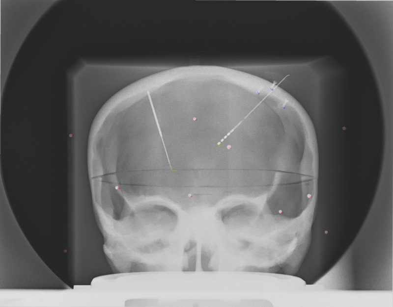
Figure 4. AP X-ray of phantom after the 20 mm displacement of the focal spot. Note the good overlap of the projection points (red dots) with the objects (spheres, screw tips, electrode tips) on the image that were slightly displaced from the previous image (Figure 2). This was accomplished by only changing the point source location, indicating that the fiducials on the display plane were predictable in this fixed setup.
AP: Antero-Posterior; mm: millimeter

