
Figure 34:
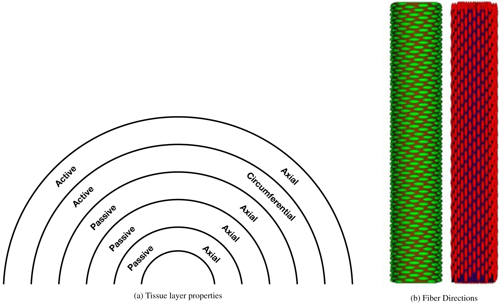
Diagram depicting properties of each layer of the esophageal model and the fiber directions used in that model (not drawn to scale). The esophageal tube is shown from a top down view in panel (a). A label of “passive” means that the passive model, equations (70 – 73), is used in that region, whereas a label of “active” means that the active model, equations (74 – 77), is used in that region. “Axial” and “circumferential” mean the fibers run in those directions, respectively. Panel (b) shows fibers running in the circumferential direction, which is used for the fourth layer, and fibers running in the axial direction, which is used for all other layers. The diagrams in panel (b) were previously reported in a work by Kou et al. [14]