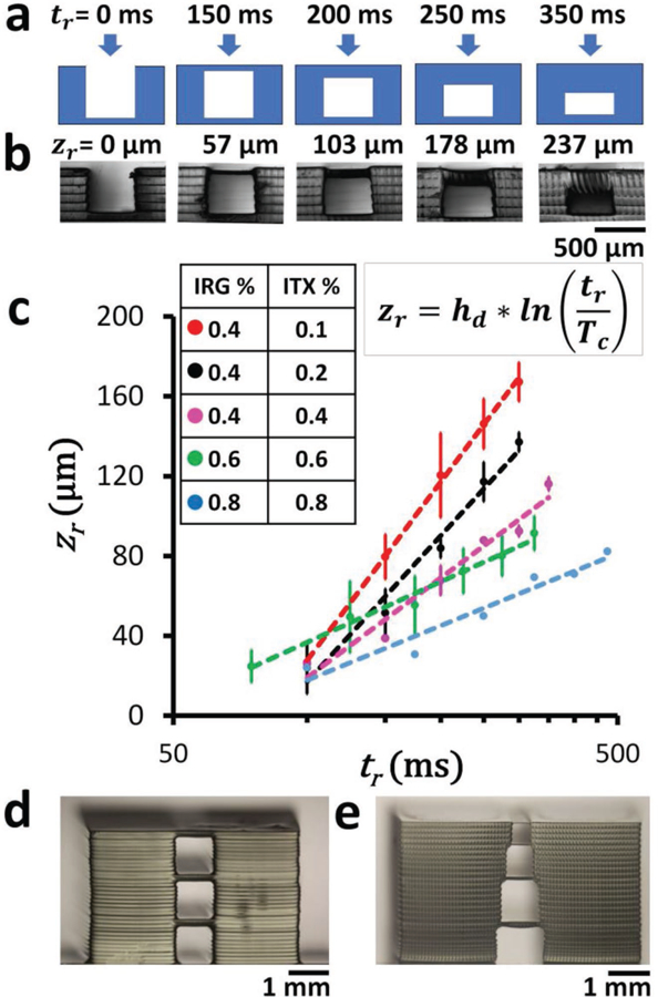
Figure 3.

Z resolution. a) Cross-sectional schematic of the photopolymerization of flat roof layers over a 500 µm wide gap supported by 200 µm wide walls. Different times of exposure (tr) will result in roofs of different thicknesses, according to Equation (2). b) Phase-contrast micrographs of the side views of 3D-printed structures printed with 0.4% IRG and 0.2% ITX PEG-DA-258 resin. The measured thickness of the polymerized roof structures zr is displayed above each image corresponding to the different times of exposure tr shown in (a). c) Log-linear plot of the thickness of 3D-printed roofs (zr) with respect to exposure times (tr) for different resin compositions ([0.4% IRG + 0.1% ITX], [0.4% IRG + 0.2% ITX], [0.4% IRG + 0.4% ITX], [0.6% IRG + 0.6% ITX], [0.8% IRG + 0.8% ITX]). Error bars denote standard deviations. d) 3D-printed stacked 1 mm square cross-sectional channels, separated by 100 µm roofs. The roofs are printed with a single 100 µm thick Z-layer using PEG-DA-258 resin with 0.4% IRG and 0.4% ITX. e) 3D-printed stacked channels with progressively reduced square cross sections (1, 0.8, 0.6, and 0.4 mm) separated by 50 µm roofs. The roofs are printed with a single 50 µm thick Z-layer using PEG-DA-258 resin with 0.4% IRG and 0.4% ITX.
