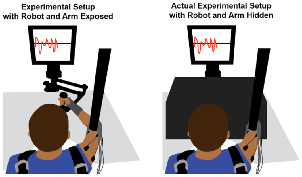
Figure 2.

Experimental Setup. The panel on the left shows how subjects held onto the planar InMotion 2 robot to perform the task. During the actual experiment, however, the view of the robot and subject’s arm was occluded by a wooden box draped with black cloth as shown in the right panel. Subjects were instructed to match their current tangential speed with a target value, both of which were displayed to the subject on a computer monitor.
