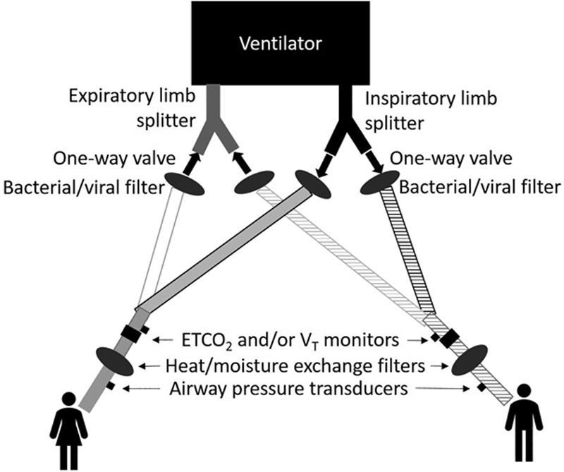
Fig. 1.

Shared ventilation circuit diagram. Selected circuit components highlighting inclusion of, for each circuit: (1) inspiratory and expiratory limb one-way valves, (2) bacterial/viral filters (protection for ventilator and shared patient), (3) end-tidal carbon dioxide (ETco2) and/or tidal volume (VT) monitoring on patient side of circuit wye, (4) heat and moisture exchange filters, and (5) airway pressure monitoring, using a dry pressure transducer directly connected (no tubing) to a side-stream Luer lock port (gas sampling port) on patient side of heat and moisture exchange filters, if possible, which allows detection of diminished airway pressures if heat and moisture exchange filters saturate and add resistance.
