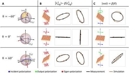
Fig. 3. Measurement results at the angles of incidence θ = −60∘,0∘,and 60∘.

(A) Polarization space representation of the device functionality. At each angle, the device induces a rotation (blue arrows) on the Poincaré sphere, which converts the input polarization (∣H⟩, blue dots) to the output polarization states (∣out⟩, green dots). The rotation axis (red arrows) is determined by the device’s eigen-polarization states (, red dots). (B) Measured (black) and simulated (brown) eigen-polarization states (). One can see that at ±60∘, the device is elliptically birefringent [corresponding to the out-of-equatorial-plane rotation axis in (A)], whereas at normal incidence, the device is linearly birefringent. At each angle, the two eigen-polarization states, and are approximately orthogonal to each other. Note that the eigen-polarization states at ±60∘ have opposite handedness. (C) Measured (black) and simulated (brown) output polarization states (∣out⟩) for a fixed incident polarization ∣H⟩. By design, the output polarization becomes right circular polarization, horizontal linear polarization, and 45° linear polarization at θ = −60∘,0∘, and 60∘ respectively. The measured DOCP (14) is 0.94 at −60∘. The measured DOLP (14) is 0.99 and 0.96 at θ = 0∘,60∘ respectively.
